НАПРЯЖЁННО-ДЕФОРМИРОВАННОЕ СОСТОЯНИЕ СТЕНКИ СТАКАНА ПРИ ОСЕСИММЕТРИЧНОЙ ГЛУБОКОЙ ВЫТЯЖКЕ С УЧЁТОМ ЗАЗОРА ИНСТРУМЕНТА, РАДИУСА МАТРИЦЫ И УСИЛИЯ ПРИЖИМА
НАПРЯЖЁННО-ДЕФОРМИРОВАННОЕ СОСТОЯНИЕ СТЕНКИ СТАКАНА ПРИ ОСЕСИММЕТРИЧНОЙ ГЛУБОКОЙ ВЫТЯЖКЕ С УЧЁТОМ ЗАЗОРА ИНСТРУМЕНТА, РАДИУСА МАТРИЦЫ И УСИЛИЯ ПРИЖИМА

Аннотация
Напряжённо-деформированное состояние стенки вытянутого стакана играет ключевую роль в процессе осесимметричной глубокой вытяжки, однако в аналитических и численных исследованиях оно часто упрощается до одноосного растяжения. В настоящей работе выполнено численное исследование напряжённо-деформированного состояния стенки стакана на основе осесимметричного моделирования методом конечных элементов в программном комплексе DEFORM-2D с целью оценки корректности данного допущения. Влияние зазора между пуансоном и матрицей, радиуса закругления матрицы и усилия прижима заготовки изучалось с использованием плана Бокса–Бенкена как структурированного способа исследования пространства технологических параметров. Компоненты напряжений и деформаций извлекались в трёх характерных точках по толщине стенки, со стороны пуансона, в средней плоскости и со стороны матрицы, на одинаковой стадии формообразования, соответствующей моменту устойчивого формирования стенки стакана. Для характеристики локального механического состояния анализировались главные напряжения, главные деформации, эквивалентное напряжение и коэффициент трёхосности напряжений. Полученные результаты выявили выраженную неоднородность напряжённо-деформированного состояния по толщине стенки. Область со стороны пуансона характеризуется преобладанием сжимающих или смешанных напряжённых состояний, срединная зона демонстрирует плосконапряжённое состояние с двухосным растяжением, которое при больших зазорах может приближаться, но не достигает одноосного растяжения, тогда как зона со стороны матрицы отличается устойчивым растягивающим состоянием с низкой чувствительностью к технологическим параметрам. Во всём исследованном диапазоне условий строго одноосное растягивающее напряжённое состояние в стенке стакана не наблюдается. Полученные результаты уточняют механическую интерпретацию процесса глубокой вытяжки и подчёркивают ограниченность упрощённых допущений об одноосном напряжённом состоянии, а также необходимость трёхмерного анализа напряжений для корректного описания локального поведения материала.
1. Introduction
Axisymmetric deep drawing is a fundamental sheet metal forming process widely used for manufacturing thin-walled cylindrical components in automotive, aerospace, and general mechanical engineering applications. During forming, a flat circular blank undergoes large plastic deformation accompanied by a complex multiaxial stress–strain state that varies significantly across different regions of the workpiece . Among these regions, the cup wall plays a central mechanical role, as it is subjected to combined axial tensile stress, circumferential tensile or compressive stress, and contact pressure transmitted through the forming tools , .
From the perspective of forming mechanics, the stress–strain state developed in the cup wall governs key technological outcomes such as thickness evolution, strain localization, and fracture tendency, as highlighted in recent numerical studies that correlate detailed stress and strain distribution with formability and fracture behavior , , and large benchmark investigations demonstrating the predictive capability of FEM in capturing stress–strain evolution and associated forming responses . Previous analytical and numerical investigations have shown that this response is strongly affected by tool geometry and boundary conditions, including punch–die clearance, die corner radius, and blank-holder force, which control material flow, bending–unbending severity, and contact stresses acting on the cylindrical wall , .
With the advancement of finite element methods, numerical simulation has become an indispensable tool for analyzing deep drawing processes and evaluating forming load, thickness variation, and stress distribution under different process parameters , , . Numerous studies have focused on optimizing geometric and process parameters such as punch radius, die radius, clearance, and blank-holder force in order to control stress distribution and thickness variation in deep drawing processes , , . However, many of these investigations primarily evaluate equivalent stress measures (e.g., von Mises stress) or overall deformation responses, with limited attention given to the systematic analysis of individual stress components or the local multiaxial stress state across the cup wall thickness.
The blank-holder force plays a complementary role by controlling compressive hoop stresses in the flange and regulating material feed into the die cavity , . While insufficient holding force promotes flange instability, excessive force increases axial tensile stress in the cup wall and accelerates thinning . Similarly, the die corner radius governs the severity of bending and unbending deformation as the sheet enters the wall region, thereby influencing the local stress path experienced by the material .
Despite extensive research on deep drawing, most existing studies primarily emphasize global forming responses such as punch force, thickness reduction, or defect occurrence , , . Recent contributions have advanced constitutive modeling and defect control strategies, including energy-based wrinkling criteria and stress-state regulation approaches in modified deep drawing processes , as well as crystal-plasticity simulations for predicting anisotropic flow behavior and limiting drawing ratio under complex biaxial stress states . However, systematic investigations of the local stress–strain state across the thickness of the cup wall remain relatively limited, particularly under controlled variations of tool clearance, die radius, and blank-holder force. In particular, the evolution of principal stresses and hydrostatic stress components in the wall region has seldom been explicitly examined, and simplified near-uniaxial or plane-stress assumptions are often implicitly adopted , , . As a result, the three-dimensional multiaxial nature of the wall stress state may be insufficiently clarified.
Although the assumption of plane stress or near-uniaxial tension in the cup wall is widely adopted in analytical models and shell-based numerical simulations, its validity has rarely been examined through solid-element stress analysis at representative through-thickness locations. In particular, the evolution of principal stresses and stress triaxiality across the wall thickness under controlled variations of punch–die clearance and die geometry has not been systematically clarified. As a result, the actual multiaxial nature of the wall stress state may be oversimplified in conventional formulations, potentially affecting the interpretation of thinning, instability, and fracture mechanisms.
Therefore, the present study aims to numerically investigate the stress–strain state of the cup wall in axisymmetric deep drawing under the combined influence of tool clearance, die corner radius, and blank-holder force. Finite element simulations using DEFORM-2D are employed to characterize the principal stresses, hydrostatic stress, equivalent stress, and plastic strain at a forming stage corresponding to the onset of cup wall formation. This reference state is geometrically defined as the moment when the center of the punch corner radius coincides with the center of the die corner radius along the axis of symmetry, which marks the transition from bending-dominated deformation over the tool radii to axial drawing of the wall. By adopting this mechanically consistent reference, the study enables a meaningful comparison of stress–strain states despite different deformation paths induced by variations in clearance and die radius. Particular attention is given to through-thickness stress–strain gradients by examining the outer surface, mid-thickness, and inner surface of the cup wall. On this basis, the work examines whether the wall stress state can evolve between biaxial tension and uniaxial tension, and critically reassesses the validity of the commonly adopted uniaxial tensile assumption in simplified analyses of deep drawing.
The main contribution of this work is to provide a systematic stress-state-based analysis of the cylindrical cup wall in conventional deep drawing. By explicitly examining the evolution of individual stress components and the resulting multiaxial stress condition under different tool geometries and boundary conditions, the study offers a mechanics-oriented interpretation of parameter effects that complements existing optimization-focused investigations.
2. Material and method
In the present study, AA5052 aluminum alloy was selected as the workpiece material. It was modeled as an isotropic plastic solid based on the tabular flow-stress data provided in the DEFORM-2D material library under cold forming conditions at 20 °C. The tabular definition allows the finite-element solver to interpolate the true stress–strain behavior directly from experimental data, ensuring accurate representation of the flow stress during large plastic deformation. The assumption of isotropic plasticity is widely adopted for annealed Al–Mg alloys and is considered adequate for predicting their mechanical response under axisymmetric cold-forming conditions. Elastic behavior was modeled with a Young’s modulus of 70 GPa and a Poisson’s ratio of 0,33. Since the forming operation was performed at room temperature and at a relatively low punch velocity, strain-rate sensitivity and thermal effects were considered negligible and therefore omitted from the analysis.
The axisymmetric deep drawing process was simulated using the DEFORM-2D finite element software. The numerical model consisted of a circular blank, a punch, a die, and a blank holder arranged in an axisymmetric configuration. The geometrical layout of the forming tools and the initial blank, including the punch–die clearance, die corner radius, and blank-holder arrangement, is illustrated in Figure 1a.
The blank was modeled as a deformable body with an initial diameter of 90 mm and a thickness S0=1,0 mm, whereas the punch, die, and blank-holder were treated as rigid tools. The punch diameter was 55,8 mm, and its corner radius was fixed at 4 mm, corresponding to four times the sheet thickness.
All simulations were performed under cold forming conditions at an ambient temperature of 20 °C. The punch velocity was maintained at 10 mm·s⁻¹, while the die and blank-holder remained stationary throughout the process. Contact between the blank and the forming tools was described using the shear friction law with a constant friction coefficient of μ=0,2, representing lightly lubricated aluminum sheet forming , . Thermal effects were neglected, and all tools were treated as adiabatic boundaries .
The blank was discretized using a quadrilateral finite element mesh comprising approximately 2880 elements with a uniform element size ratio of 1,0. The initial finite element discretization of the deformable blank is shown in Figure 1b. Adaptive remeshing was activated during the simulation to prevent excessive element distortion under large plastic deformation. The simulations were carried out using an implicit Lagrangian formulation with an incremental punch displacement of 0,1 mm per step.
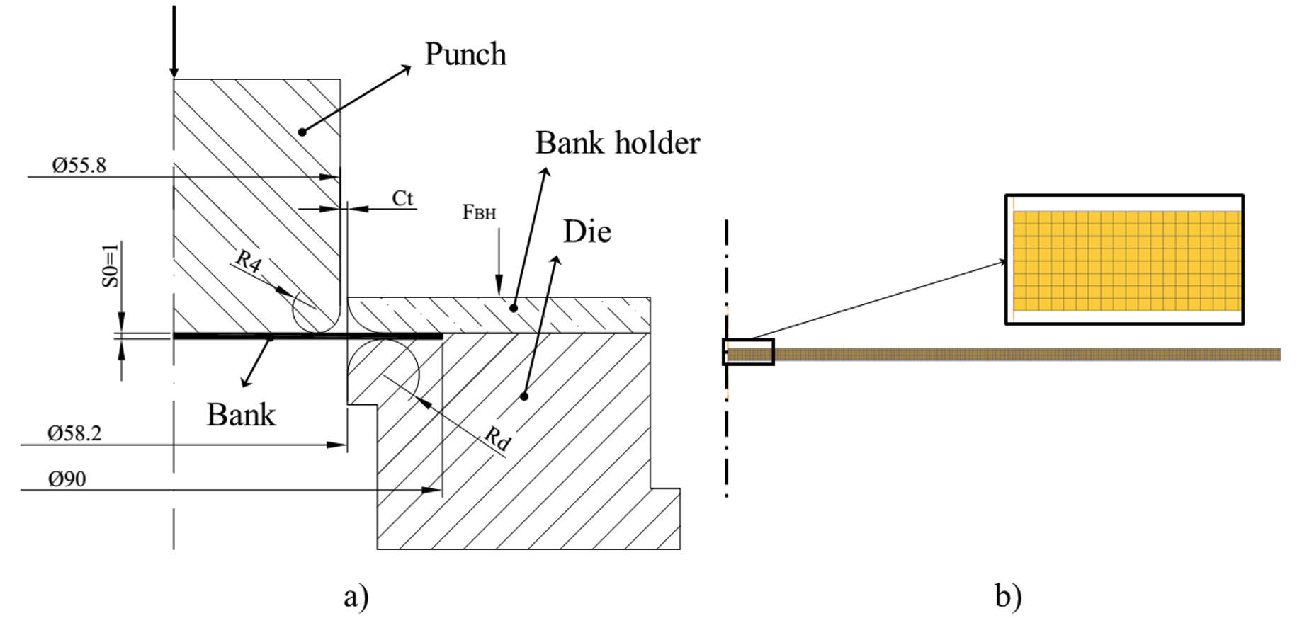
Numerical model of the axisymmetric deep drawing process:
a) Geometrical configuration of the punch, die, blank holder, and blank; b) Finite element discretization of the deformable blank
The investigated process parameters were selected based on commonly recommended ranges for aluminum alloy deep drawing reported in the literature , . The die corner radius was varied in normalized form as Rd/S0 = 5, 6, 7, while the normalized punch–die clearance was expressed as Ct/S0 = 1,0, 1,2, 1,4. A uniformly distributed blank-holder force (FBH) of 2000, 2500, and 3000 N was applied to regulate material flow from the flange region and to prevent wrinkling or premature fracture.
A numerical experimental design based on the Box–Behnken Design (BBD) was employed to systematically investigate the influence of process parameters on the stress–strain state at the cup wall. Each factor was assigned three levels, corresponding to the low (–1), middle (0), and high (+1) values listed in Table 1.
Table 1 - Process parameters and their levels used in the Box–Behnken design
Factor | Symbol | Unit | Level -1 | Level 0 | Level +1 |
Normalized die clearance | (Ct/S0) | – | 1,0 | 1,2 | 1,4 |
Die corner radius | (Rd/S0) | mm | 5 | 6 | 7 |
Blank-holder force | (FBH) | N | 2000 | 2500 | 3000 |
The adopted Box–Behnken design resulted in a total of 15 simulation runs, including 12 edge points and three replicates at the center point (Ct/S0=1,2, Rd/S0=6 mm, FBH=2500 N). To assess the sensitivity of the numerical model to interfacial conditions, the center-point simulations were repeated with slightly varied friction coefficients (μ=0,195, 0,200, 0,205). This strategy provides a practical estimate of the numerical variability of the forming responses under nearly identical process conditions, without introducing artificial random noise.
All simulations were performed under identical modeling assumptions and boundary conditions. To ensure a consistent and mechanically meaningful comparison among different design points, the stress–strain state was evaluated at a forming stage corresponding to the onset of cup wall formation. This stage was geometrically defined as the moment when the center of the punch corner radius coincides with the center of the die corner radius along the axis of symmetry. This condition represents the transition from bending-dominated deformation over the tool radii to axial drawing of the cup wall and provides a uniform reference state for assessing the stress–strain characteristics of the wall under different combinations of tool clearance, die corner radius, and blank-holder force.
The cup wall was defined as the cylindrical region formed between the punch corner radius and the die corner radius, excluding the fillet zones associated with bending and unbending deformation. To ensure a consistent and physically meaningful comparison among all simulations, stress–strain data were extracted at a fixed punch stroke of 13 mm, corresponding to the stage at which the cylindrical wall is clearly formed. At this forming stage, a cross-section located 5 mm above the cup bottom was selected to avoid the influence of bottom bending effects. Within this cross-section, three representative material points were defined across the sheet thickness. The reference point P2 was first identified at the mid-thickness position, defined as the midpoint between the punch-side and die-side working surfaces. Two additional points, P1 and P3, were then obtained by offsetting P2 by ±0,4 mm along the thickness direction, toward the punch side and the die side, respectively. Accordingly, P1 and P3 represent subsurface locations adjacent to the inner and outer surfaces of the cup wall, respectively, as illustrated in Figure 2.
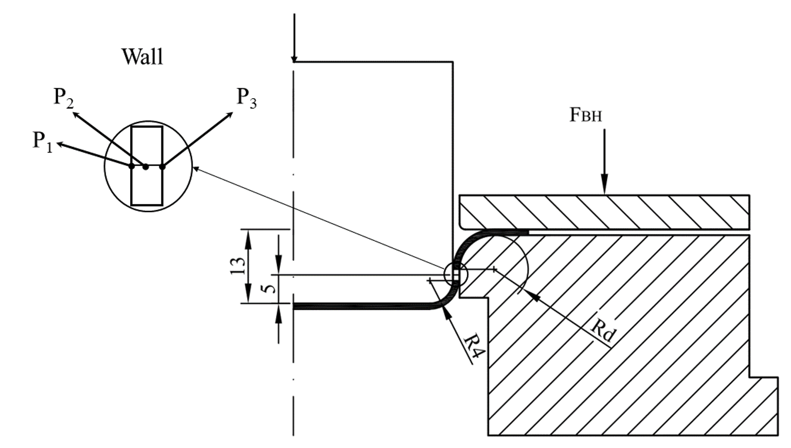
Definition of the cup wall region and selection of representative through-thickness points (P1–P3) at a punch stroke of 13 mm
At each observation point, the principal and equivalent stress and strain components were extracted from the finite element results. Specifically, the maximum (σ1) and minimum (σ3) principal stresses, the mean (hydrostatic) stress σm = (σ1 + σ2 + σ3)/3, the equivalent von Mises stress (σeq), and the major (ε1) and minor (ε3) principal strains were recorded to characterize the local stress–strain state during the forming process. Based on these quantities, the intermediate principal stress (σ2) was determined from the definition of the hydrostatic stress, while the intermediate principal strain (ε2) was obtained from the incompressibility condition of plastic deformation. Using the extracted stress components, stress triaxiality was employed as a scalar descriptor of the local stress state and was calculated according to
where σm is the mean (hydrostatic) stress and σeq is the equivalent von Mises stress. Stress triaxiality was employed as a compact indicator of the local stress state, allowing direct comparison between different forming conditions and locations through the wall thickness. For each reference point (P1, P2, and P3), tabulated datasets were established containing the principal stresses, principal strains, equivalent stress, and the corresponding stress triaxiality values. These tables form the basis for the subsequent analysis of stress–strain states in the cup wall and enable a systematic comparison across the entire numerical design space.
It should be emphasized that the present study does not aim to construct a predictive constitutive or regression-based model. Instead, the Box–Behnken design was employed as a structured sampling strategy to explore the three-dimensional process parameter space defined by the normalized punch–die clearance (Ct/S0), the normalized die corner radius (Rd/S0), and the blank-holder force (FBH). This approach allows the identification of trends, stability, and possible transitions in the local stress–strain state of the cup wall without introducing additional modeling assumptions.
3. Results and discussion
Figure 3 presents the evolution of the maximum principal stress at the three representative points P1, P2, and P3 during the deep drawing process, together with its spatial distribution in the cup wall at the reference forming stage defined in Section 2. The time histories reflect the successive deformation stages experienced by the material, including initial bending over the tool radii, unbending, and subsequent axial drawing of the cylindrical wall. The contour plot shows the distribution of the maximum principal stress over the entire blank at the reference forming stage, with the observation points P1–P3 located in a mechanically stable region of the cup wall.
At the selected reference stage (punch stroke of 13 mm), the stress–strain state is evaluated at identical material locations for all simulations. Using the same point-tracking procedure, the principal stresses, principal strains, equivalent stress, and stress triaxiality were extracted for all combinations of punch–die clearance, die corner radius, and blank-holder force. The resulting datasets form the basis for the following analysis.
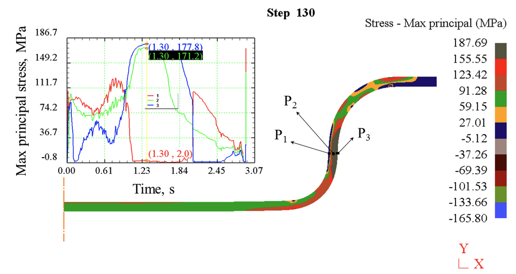
Evolution of the maximum principal stress at representative points P1–P3 during the deep drawing process and its distribution in the cup wall at the reference forming stage
Table 2 - Stress state at point P1 (subsurface location near the punch side) under different forming conditions
Run | Ct/S0 | Rd/S0 | FBH (N) | σ1 (Mpa) | σ2 (Mpa) | σ3 (Mpa) | η |
1 | 1 | 5 | 2500 | 80,8 | 57,69 | -1,6 | 0,62 |
2 | 1,4 | 5 | 2500 | -0,25 | -90,65 | -164,7 | -0,597 |
3 | 1 | 7 | 2500 | -0,42 | -72,61 | -111,89 | -0,629 |
4 | 1,4 | 7 | 2500 | 0,196 | -75,816 | -170,23 | -0,554 |
5 | 1 | 6 | 2000 | 25,6 | 17,66 | -13,26 | 0,281 |
6 | 1,4 | 6 | 2000 | -0,16 | -88,6 | -163,9 | -0,593 |
7 | 1 | 6 | 3000 | 68,5 | 41,9 | -5,1 | 0,544 |
8 | 1,4 | 6 | 3000 | -0,5 | -56,6 | -163,7 | -0,512 |
9 | 1,2 | 5 | 2000 | 1,6 | -113,3 | -159,5 | -0,629 |
10 | 1,2 | 7 | 2000 | 1,3 | -95,3 | -157,4 | -0,605 |
11 | 1,2 | 5 | 3000 | 1,8 | -74,1 | -132,3 | -0,586 |
12 | 1,2 | 7 | 3000 | 1,4 | -89,5 | -157,3 | -0,593 |
13 | 1,2 | 6 | 2500 | 1,6 | -98,6 | -152,6 | -0,614 |
14 | 1,2 | 6 | 2500 | 1,1 | -85,4 | -150,3 | -0,594 |
15 | 1,2 | 6 | 2500 | 2 | -100,3 | -151,9 | -0,615 |
In contrast, a limited number of simulations (Runs 1, 5, and 7), characterized by a small punch–die clearance (Ct/S₀ = 1) combined with relatively small die corner radii (Rd/S₀ = 5 or 6), exhibit a markedly different stress state. In these cases, the maximum principal stress σ₁ becomes significantly positive, while the minimum principal stress σ₃ remains slightly negative and close to zero, indicating a biaxial tensile stress state rather than a purely compressive one. The corresponding stress triaxiality values (η ≈ 0,62, 0,281, and 0,544) are clearly positive and substantially higher than zero, confirming the transition toward a tensile-dominated regime. However, these values remain distinct from the classical uniaxial tension condition, for which η = 1/3.
The emergence of this tensile-dominated stress state can be explained by the combined effect of restricted material flow and continued punch penetration. Under small clearance conditions, material thickening in the flange region reduces the ability of the sheet to flow into the narrow punch–die clearance. As the punch continues to advance, tensile stresses develop locally at the inner wall, leading to the observed increase in σ₁ and stress triaxiality. It is noteworthy that Run 3, although conducted at the same small clearance (Ct/S₀ = 1), does not exhibit a similar transition toward a tensile-dominated stress state due to the larger die corner radius (Rd/S₀ = 7). A larger die radius alleviates the severity of bending–unbending deformation and facilitates smoother material flow into the punch–die gap. As a result, the thickening effect in the flange region and its consequent obstruction of material flow through the narrow clearance develops at a later stage of deformation. Under the selected reference forming condition, the stress state at P1 therefore remains dominated by biaxial compression, consistent with the majority of forming conditions in the design space.
Overall, within the investigated deep drawing design space where no wall thinning is observed, the stress state at point P1 is predominantly governed by biaxial or triaxial compression. This finding cannot be captured by conventional shell-based forming simulations that rely on mid-surface assumptions and plane-stress conditions, as commonly adopted in previous studies
. The present axisymmetric solid-based analysis therefore provides additional insight into the local three-dimensional stress state at the punch–wall interface.The strain-state results at point P1 summarized in Table 3 reveal a consistent deformation pattern across the investigated forming conditions. For the majority of simulations, the strain state at P1 is characterized by one dominant tensile principal strain (ε₁ > 0), accompanied by one compressive principal strain (ε₃ < 0), while the intermediate principal strain ε₂ remains comparatively small. This strain configuration corresponds to a combined tensile–compressive deformation mode rather than a uniaxial tensile state.
This behavior is mechanically consistent with the compression-dominated or biaxial stress state identified at P1 for most design points. The compressive contact pressure exerted by the punch constrains through-thickness expansion and suppresses the development of a purely tensile strain mode at the inner wall. As a result, deformation at P1 proceeds under a mixed loading condition involving axial stretching combined with lateral compression.
Table 3 - Strain state at point P1 (subsurface location near the punch side)
Run | Ct/S0 | Rd/S0 | FBH (N) | ε1 | ε2 | ε3 |
1 | 1 | 5 | 2500 | 0,1602 | -0,0543 | -0,1059 |
2 | 1,4 | 5 | 2500 | 0,0957 | 0,0072 | -0,1029 |
3 | 1 | 7 | 2500 | 0,1504 | -0,0436 | -0,1068 |
4 | 1,4 | 7 | 2500 | 0,0852 | 0,0164 | -0,1016 |
5 | 1 | 6 | 2000 | 0,1488 | -0,0415 | -0,1073 |
6 | 1,4 | 6 | 2000 | 0,0888 | 0,0141 | -0,1029 |
7 | 1 | 6 | 3000 | 0,1519 | -0,0456 | -0,1063 |
8 | 1,4 | 6 | 3000 | 0,083 | 0,0206 | -0,1036 |
9 | 1,2 | 5 | 2000 | 0,1194 | -0,014 | -0,1054 |
10 | 1,2 | 7 | 2000 | 0,1033 | 0,0017 | -0,105 |
11 | 1,2 | 5 | 3000 | 0,1195 | -0,0145 | -0,105 |
12 | 1,2 | 7 | 3000 | 0,1049 | -0,0005 | -0,1044 |
13 | 1,2 | 6 | 2500 | 0,1086 | -0,0031 | -0,1055 |
14 | 1,2 | 6 | 2500 | 0,1088 | -0,0032 | -0,1056 |
15 | 1,2 | 6 | 2500 | 0,1085 | -0,0029 | -0,1056 |
An examination of the strain components listed in Table 3 indicates that Runs 1, 3, 5, and 7 exhibit a highly similar deformation mode at point P1. In all these cases, the major principal strain ε₁ is positive, while both the intermediate and minor principal strains (ε₂ and ε₃) remain negative. This strain configuration corresponds to a mixed tensile–compressive deformation mode characterized by one tensile and two compressive strain components.
Although Runs 1, 3, 5, and 7 exhibit a similar strain mode at point P1, characterized by one tensile and two compressive principal strains, their stress states differ markedly. This apparent discrepancy arises from the fact that strain describes the kinematics of deformation, whereas stress is strongly influenced by local contact conditions and constraint severity. In Run 3, the larger die corner radius promotes smoother bending and material flow, thereby maintaining higher compressive contact pressure at the punch–wall interface. As a result, the stress state remains compression-dominated despite a strain mode similar to that observed in Runs 1, 5, and 7. This observation highlights that identical strain paths do not necessarily correspond to identical stress states in deep drawing, particularly under varying tool geometries and clearance conditions.
Overall, the results at point P1 demonstrate that the assumption of uniaxial tensile stress is not appropriate for describing the mechanical state at the inner wall of the cup. For most forming conditions within the investigated design space, the stress state at P1 is dominated by biaxial compression, while the corresponding strain state is characterized by a mixed mode involving one tensile and one compressive principal strain, consistent with a plane-strain–like deformation state.
When the punch–die clearance is reduced to Ct/S₀ = 1, a partial transition in the stress state is observed, with the development of a mild plane-tensile stress condition. However, even in these cases, the deformation remains three-dimensional, as evidenced by the simultaneous presence of significant compressive components in the intermediate and minor principal strains. These findings indicate that the mechanical response at the punch–wall interface is governed by the combined effects of axial drawing and strong compressive contact, rather than by a uniaxial tensile loading mode.
The stress–strain states evaluated at point P2, located at the mid-thickness of the cup wall, are summarized in Table 4. For the majority of the investigated forming conditions, the stress state is characterized by a dominant tensile maximum principal stress σ₁, while the minimum principal stress σ₃ remains slightly compressive with a magnitude close to zero. This stress configuration is representative of a plane-stress–dominated condition, in which biaxial tension develops within the sheet plane and the through-thickness stress is negligible. Such a stress state is widely reported for the cup wall region in axisymmetric deep drawing and is consistent with classical analytical and numerical descriptions of the process
, , .From the deformation perspective, the strain state at P2 exhibits a well-defined hierarchy among the principal components. The major principal strain ε₁ is tensile and associated with axial stretching along the drawing direction. The minor principal strain ε₃ shows a relatively large compressive magnitude, corresponding to thickness reduction imposed by plastic incompressibility. In contrast, the intermediate principal strain ε₂, associated with the circumferential (tangential) direction, remains compressive but significantly smaller in magnitude than both ε₁ and ε₃.
This strain configuration is mechanically consistent with the classical description of deformation in the cup wall
. According to Banabic and co-workers, the wall region of a drawn cup typically experiences a deformation mode close to plane strain or plane stress with dominant thickness compression, where thinning is the primary compensating mechanism for axial stretching, while circumferential strain remains weakly constrained. Similar conclusions are reported in analytical and experimental studies on cylindrical cup drawing, where ε₃ governs thickness evolution, ε₁ controls axial elongation, and ε₂ plays a secondary role , .Table 4 - Stress–strain state at point P2 (mid-thickness of the cup wall)
Run | σ1 (Mpa) | σ2 (Mpa) | σ3 (Mpa) | η | ε1 | ε2 | ε3 |
1 | 104,32 | 64,48 | -8,3 | 0,541 | 0,1626 | -0,0705 | -0,0921 |
2 | 159,3 | 23,9 | -4,1 | 0,394 | 0,1109 | -0,0207 | -0,0902 |
3 | 179,8 | 79,9 | 1,9 | 0,565 | 0,124 | -0,0307 | -0,0933 |
4 | 137,4 | -2,5 | -18,5 | 0,261 | 0,0927 | -0,0014 | -0,0913 |
5 | 117,1 | 58 | -20,9 | 0,429 | 0,1454 | -0,0519 | -0,0935 |
6 | 154,7 | 14,4 | -3,8 | 0,367 | 0,1018 | -0,0109 | -0,0909 |
7 | 131,3 | 59,92 | -27,6 | 0,396 | 0,1538 | -0,0612 | -0,0926 |
8 | 149,1 | 0,74 | -2,84 | 0,326 | 0,098 | -0,0067 | -0,0913 |
9 | 168,5 | 42,7 | -2,4 | 0,454 | 0,1298 | -0,0376 | -0,0922 |
10 | 164 | 32,44 | -0,24 | 0,434 | 0,1023 | -0,009 | -0,0933 |
11 | 168,5 | 42,7 | -2,1 | 0,455 | 0,1301 | -0,0384 | -0,0917 |
12 | 164,4 | 33,23 | -0,23 | 0,437 | 0,1037 | -0,0109 | -0,0928 |
13 | 170,1 | 54 | -1,8 | 0,488 | 0,1143 | -0,0218 | -0,0925 |
14 | 170,7 | 54,1 | -1,9 | 0,487 | 0,1142 | -0,0216 | -0,0926 |
15 | 171,2 | 55,1 | -1,6 | 0,491 | 0,1142 | -0,0216 | -0,0926 |
A distinct mechanical response is observed for Runs 2, 4, 6, and 8, which are all associated with the largest punch–die clearance investigated (Ct/S₀ = 1,4). In these cases, the maximum principal stress σ₁ attains relatively high positive values, while the remaining two principal stresses are significantly smaller in magnitude. This stress configuration corresponds to a biaxial tensile state characterized by a dominant axial stress σ₁ and a strongly reduced circumferential stress σ₂, which is consistent with the nearly zero intermediate principal strain ε₂ and indicates a deformation mode approaching uniaxial tension.
The stress triaxiality values for these runs do not coincide exactly with the ideal uniaxial tension value of 1/3; instead, they scatter slightly above or below this reference, depending on the specific forming condition. This indicates that the stress state at P2 under large-clearance conditions represents a transitional regime between plane-stress biaxial tension and ideal uniaxial tension, rather than a strictly uniaxial state. Similar stress-state transitions in the cup wall, associated with a reduction in lateral constraint, have been discussed in classical analytical and numerical descriptions of deep drawing
, .The emergence of this behavior can be attributed to the reduced mechanical confinement associated with a large punch–die clearance. As Ct/S₀ increases, contact pressures decrease and circumferential constraint is relaxed, allowing the material to deform predominantly by axial stretching and thickness reduction. Under such conditions, the plane-stress assumption inherent to shell and midsurface formulations becomes less severely challenged, which explains why these approaches generally provide reasonable predictions of global deformation and forming limits, even though they cannot resolve strong through-thickness stress gradients near contact interfaces.
The stress–strain states evaluated at point P3, located near the outer surface of the cup wall adjacent to the die, are summarized in Table 5. Compared to the inner-wall point P1 and the mid-thickness point P2, the mechanical response at P3 exhibits a more stable and uniform character across the investigated design space.
From a stress perspective, the maximum principal stress σ₁ at P3 remains consistently positive and relatively high for all forming conditions, while the intermediate principal stress σ₂ is also tensile but of smaller magnitude. In contrast, the minimum principal stress σ₃ is close to zero or slightly compressive. This stress configuration corresponds to a plane-stress–dominated state with biaxial tension in the sheet plane, similar in nature to the response observed at P2, but with a reduced influence of contact-induced compressive stresses.
The associated stress triaxiality values at P3 remain positive and confined to a narrow range, indicating a stable tensile stress state with limited sensitivity to variations in punch–die clearance, die corner radius, or blank-holder force. Unlike the inner-wall point P1, no transition toward compression-dominated stress states is observed at P3, even under small-clearance conditions. This behavior reflects the fact that the outer surface of the cup wall is primarily constrained by the die geometry rather than by direct punch contact, leading to a smoother and more uniform stress evolution.
In terms of deformation, the strain state at P3 is characterized by a tensile major principal strain ε₁ associated with axial drawing, accompanied by a pronounced compressive minor principal strain ε₃ resulting from thickness reduction. The intermediate principal strain ε₂ remains compressive and of moderate magnitude, larger than that observed at P2 but still secondary relative to ε₁ and ε₃. This strain configuration indicates a stable three-dimensional deformation mode dominated by axial stretching and thickness compression, with limited circumferential strain development.
Table 5 - Stress–strain state at point P3 (subsurface location near the die side)
Run | σ1 (Mpa) | σ2 (Mpa) | σ3 (Mpa) | η | ε1 | ε2 | ε3 |
1 | 116,8 | 73,53 | -1,03 | 0,611 | 0,1703 | -0,0793 | -0,091 |
2 | 175,7 | 63,7 | -1,2 | 0,512 | 0,1252 | -0,0468 | -0,0784 |
3 | 180,5 | 85,84 | 0,96 | 0,573 | 0,1103 | -0,0297 | -0,0806 |
4 | 168,4 | 46,7 | -0,9 | 0,472 | 0,0971 | -0,0176 | -0,0795 |
5 | 174,7 | 86,9 | -8,4 | 0,532 | 0,1611 | -0,0804 | -0,0807 |
6 | 173,56 | 60,89 | -1,05 | 0,507 | 0,1127 | -0,0339 | -0,0788 |
7 | 181,4 | 88,25 | -5,95 | 0,542 | 0,1693 | -0,0799 | -0,0894 |
8 | 170,75 | 50,19 | -1,04 | 0,48 | 0,1112 | -0,0322 | -0,079 |
9 | 180,7 | 73,94 | -0,54 | 0,537 | 0,1398 | -0,0598 | -0,08 |
10 | 173,9 | 66,94 | 0,06 | 0,529 | 0,0961 | -0,0154 | -0,0807 |
11 | 180,1 | 73,1 | -0,6 | 0,535 | 0,1399 | -0,0604 | -0,0795 |
12 | 173,8 | 66,87 | -0,07 | 0,528 | 0,0975 | -0,0173 | -0,0802 |
13 | 177,7 | 76,8 | -0,4 | 0,548 | 0,1165 | -0,0363 | -0,0802 |
14 | 177,6 | 77,6 | -0,5 | 0,549 | 0,1162 | -0,036 | -0,0802 |
15 | 177,8 | 76,8 | -0,5 | 0,547 | 0,1171 | -0,0369 | -0,0802 |
The behavior observed at point P3 should be interpreted primarily from a geometric and contact-mechanics perspective rather than as a distinct deformation mode. At the selected reference forming stage, the effective punch–die clearance remains comparable to or larger than the local sheet thickness, particularly near the bottom fillet where thinning has already occurred. As a consequence, the outer surface of the cup wall has not yet established sustained contact with the cylindrical working surface of the die.
This lack of direct die–wall contact explains why the mechanical response at P3 remains relatively stable across the design space and does not exhibit strong sensitivity to variations in clearance, die radius, or blank-holder force. Unlike P1, where punch contact dominates the stress state, and P2, where the response reflects a representative mid-thickness behavior, P3 is governed mainly by global drawing kinematics at this forming stage.
Therefore, the stress–strain state at P3 should not be interpreted as a die-constrained condition, but rather as a transitional outer-wall response prior to the onset of contact with the die land. A qualitatively different stress state is expected to develop at later stages of forming, once the outer wall engages fully with the die, which lies beyond the scope of the present analysis.
Based on the stress–strain evaluation at the three representative locations across the cup wall thickness, the local mechanical states during deep drawing can be clearly classified, as summarized in Figure 4. The inner wall region (P1) is governed by a compression-dominated stress state due to direct punch contact, with predominantly negative stress triaxiality over most of the design space. The mid-thickness region (P2) exhibits a near plane-stress condition characterized by dominant axial tension and thickness compression, representing the averaged mechanical response commonly assumed in shell- and midsurface-based formulations. The outer wall region (P3) remains in a stable near plane-stress state, largely controlled by axial drawing and geometric effects, with limited sensitivity to contact conditions at the selected forming stage.
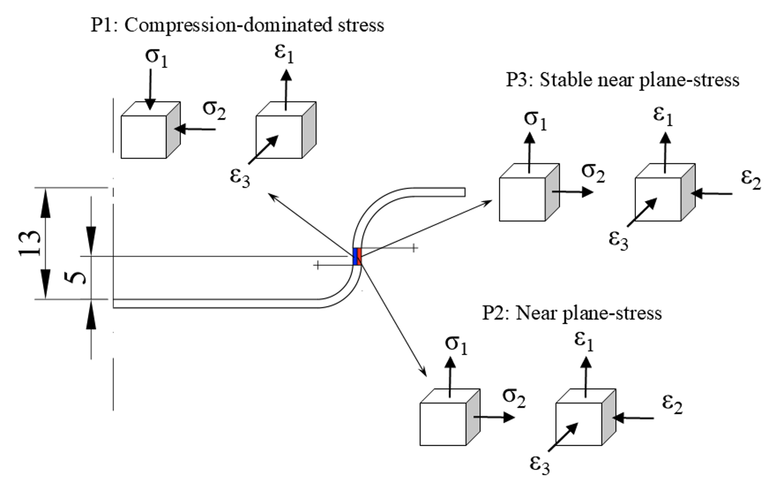
Characteristic stress–strain states across the cup wall
4. Conclusion
This study has examined the stress–strain state in the cup wall during axisymmetric deep drawing through solid-element finite element simulations combined with a structured exploration of process parameters using a Box–Behnken design. By evaluating representative material points across the wall thickness, the results demonstrate that the mechanical state of the cup wall is strongly non-uniform in the thickness direction. The region near the punch-side subsurface is governed predominantly by compressive stresses, arising from direct punch contact, and is characterized by a mixed deformation mode involving two-dimensional compression coupled with tensile–compressive strain. In contrast, the mid-thickness region exhibits a plane-stress–dominated response, with tensile stress prevailing in the drawing direction and thickness reduction governed by plastic incompressibility. The die-side subsurface shows a stable near plane-stress condition, reflecting the absence of sustained die contact at the investigated forming stage.
The analysis further reveals that punch–die clearance plays a key role in controlling transitions between stress states, particularly at the mid-thickness of the wall, where larger clearances promote stress and strain states approaching uniaxial tension, while smaller clearances preserve biaxial or compression-influenced conditions. Stress triaxiality proves to be an effective scalar indicator for distinguishing these regimes and for comparing stress states across both location and process parameter space. Overall, the results confirm that classical shell- and midsurface-based assumptions remain valid for describing the mid-thickness response of the cup wall, but they are insufficient for capturing the compression-dominated stress states that develop near contact interfaces. These findings underline the necessity of three-dimensional stress analysis when a detailed understanding of local deformation and stress evolution in deep drawing is required.
In addition to the numerical findings, this study provides a stress-state-based interpretation of parameter effects in conventional deep drawing. By explicitly analyzing the evolution of individual stress components in the cylindrical wall region, the work clarifies how tool geometry modifies the local multiaxial stress condition, which in turn governs thickness development and fracture tendency. This mechanics-oriented perspective complements existing optimization-focused studies and contributes to a deeper understanding of stress-state control in cup drawing processes.