THERMAL IMAGING METHOD AS A TYPE OF ROBOTIC DIAGNOSTICS OF HYDRAULIC EXCAVATORS
THERMAL IMAGING METHOD AS A TYPE OF ROBOTIC DIAGNOSTICS OF HYDRAULIC EXCAVATORS
Abstract
The text discusses a type of thermal diagnostics based on the use of thermal cameras for detecting defects in the main components of hydraulic excavators used in mining operations. When hydraulic drives in high-power excavators operate, they generate heat due to turbulence in the hydraulic fluid as it flows through channels, cavities, and pipelines. However, additional heating inevitably occurs when specific defects arise in hydraulic power units, such as hydraulic cylinders and hydraulic equipment like valves and other components. Furthermore, the failure of sealing elements in hydraulic cylinder rods can lead to fluid leaks, which are not visually detectable at the initial stage of defect development. However, these leaks can be identified by measuring the changing thermal background of the sealing unit due to the leaks. Additionally, when filters become clogged or dirty, their housings experience intense heating, which can also be detected by thermal cameras, allowing for early predictions of potential failures. If this diagnostic method is widely adopted, it could lead to the creation of a robotic mechanism for predicting the failure of components and units in hydraulic excavators within a specific mining enterprise.
1. Introduction
Modern means and methods of early warning (detection) of defects in the components and mechanisms of large (large unit capacity) mining machinery, e.g. quarry, walking, rotary and quarry hydraulic excavators, are based on time-consuming and long-term diagnostic measures such as vibroacoustic, ultrasonic, eddy current and other methods that are quite efficient when used during quite long-term (up to 3–5 shifts) field tests. Since the mining workflow involves large excavators, such “unplanned” downtime of mining equipment economically incurs losses. As new non–destructive testing devices emerge (thermal imagers), it is now possible to take prompt measures for non–destructive testing of operating mining equipment, such as hydraulic mining excavators, without interrupting the production cycle.
Tyazhmashservice company (Krasnoyarsk) specializing in maintenance services for mining equipment for open-pit mining has been actively using the thermal imaging diagnostic method in its activities since 2008 to detect incipient defects in quarry and walking excavators. The results of using this method are described in more detail in the corresponding articles of the author , , as well as in the textbook for universities and in the handbook for open-pit mining .
In the period from 2012 to the present, some mining enterprises began to purchase hydraulic excavators with a bucket capacity of 15 to 45 m3 for their open-pit mining operations. Such excavators are used both in transport stripping and directly in the extraction of solid minerals. As a rule, these excavators are expensive imported products, and any downtime entails serious losses for mining owners. Therefore, the technical support in the operation of such machinery is a top priority for maintenance companies servicing such machines. The early diagnostics of incipient defects for equipment of this type is becoming a very relevant technical issue. The tools of such operational diagnostics include thermal (based on contact thermal sensors of various types) and thermal imaging (based on the contactless use of modern infrared thermal imagers). Thus, the specialists of the Voronezh Industrial University inspected the components of logging machines by thermal study of their hydrostatic transmission oils . This study has shown the efficiency of using the thermal diagnostic method for fault-finding in transmission components in heavy operating conditions of forest machinery.
In addition, the thermal imaging diagnostic method has already been successfully tested in the energy engineering industry, which has been successfully used in the diagnostics of large transformers .
Taking into account our own experience in applying the thermal imaging method of non-destructive testing of quarry, walking and rotary excavators, as well as that new equipment (quarry hydraulic excavators) is actively employed at coal mines and mining enterprises of the Russian Federation, Tyazhmashservice is introducing its own method of non-destructive testing for main components and mechanisms of quarry hydraulic excavators, based on modern thermal imaging equipment and features of fluid and gas mechanics, which are typical of quarry hydraulic equipment with high installed unit capacity.
2. Main results
Hydraulic excavators of high unit capacity have occupied an ever-growing share in open-pit mining over the 40-year history of their practical operation. This is facilitated by the constant work of the manufacturers of these excavators aimed at improving the reliability of designs, the durability of individual components and mechanisms, as well as competitiveness in terms of the final cost of ownership. According to estimates by leading mining industry experts, in the near future, the share of hydraulic excavator supplies may reach 70–75% of the total excavator supply. Nevertheless, compared with electro-mechanical shovels, the total service life of hydraulic machines is 0,7–0,8x of the service life of dragline excavators. This is due to the lifetime of hydraulic drives, which, unlike mechanical and electric drives, are much more susceptible to operating conditions and the quality of maintenance. The second reason for the slightly shorter service life of hydraulic excavators compared to mechanical excavators is the low operating culture of hydraulic drives (untimely replacement of hydraulic fluid, filters, sealing assemblies, etc.). In addition, even with such a long service life of hydraulic excavators, emergency breakdowns of these machines occur very often (due to hidden defects), which reduce their already short service life compared to electromechanical excavators. That is why the issues of early warning of possible breakdowns of hydraulic drive elements in hydraulic excavators become especially important when choosing the type of excavators and the economics of their repair and maintenance cycle.
Currently, devices have been developed and are actively used in the diagnostics of technical systems of modern machines and mechanisms, requiring a short period of time to analyze the basic parameters of electrical, mechanical, hydraulic, and other drive units during the operation of a single machine. This article discusses the specifics of using the thermal (thermal imaging) diagnostic method to solve problems in troubleshooting and early warning of malfunctions of hydraulic drives of large hydraulic excavators.
There are various methods for diagnosing defects in hydraulic drives. They can be divided into direct and indirect ones. Direct methods include measurements of pressure, flow rate, and temperature of the hydraulic fluid, as well as the position and speed of the actuator. Indirect methods are vibration, noise (acoustic) characteristics, and the extent of hydraulic fluid contamination. These methods also include the intensity and variability of thermal radiation from hydraulic components and individual hydraulic devices. It is this method that is investigated in this article.
When a hydraulic excavator operates, especially one having a high unit capacity, heat is actively generated. Permanent sources of hydraulic fluid heating in hydraulic drives are pumps, shut-off and control equipment, hydraulic motors, and hydraulic cylinders. In addition to these permanent heat sources, there are additional (discretely appearing and disappearing) sources. They include:
accelerations, vortices, additional turbulence of fluid flows associated with:
– defects of plunger pairs, spools, valves;
– defects in piston rings, seals, and surfaces of pistons, rods, and cylinders;
– defects in high-pressure hoses;
– filter blockages.
Since the actual method of testing hydraulic drive elements was developed exclusively for the factory conditions of the manufacturer (and also has limited corporate availability), it is almost inapplicable in the field operating conditions of hydraulic excavators. In such conditions, it is necessary to develop from scratch a procedure for operational diagnostics (including thermal imaging diagnostics) of a real hydraulic excavator in active operation. The features of this diagnostic method of hydraulic cylinders and hydraulic devices are:
– the hydraulic drive of the actuator (bucket) must be warmed up, the bucket itself is loaded and statically stationary (the “pressure into the side of the face” position or raised with a loaded rock mass);
– spatial circular capture of the thermal image along the body of the hydraulic cylinder (on all accessible external sides).
When diagnosing high-pressure hoses and filters, the thermal image should be captured with the start of the main pumps, i.e. in the “cold” state of the hydraulic fluid.
Fig. 1 show thermal images of the piston seal of the hydraulic cylinder of the dipper drive with a bucket of 26 cubic meters (“straight shovel” type). The dipper is loaded, the operating pressure in the rod cavity is 200 atm, the drain pressure in the piston cavity is 1 atm; the temperature of the outer surface of the cylinder body in the area of its rod cavity is 17.8 °C (Fig. 1a). Fig. 1b shows the temperature of the cylinder body in the area of its piston of 18.7 °C. Fig. 1c shows the temperature of the outer surface of the cylinder body in the area of its piston cavity of 17.6 °C.
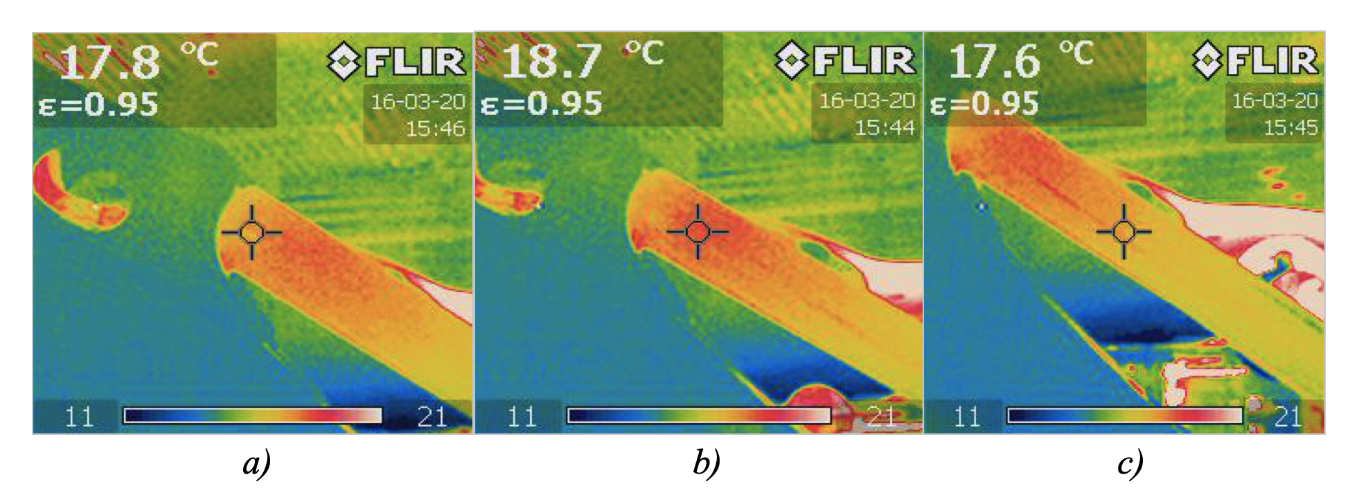
Figure 1 - Diagnosis of internal overflows across the piston seal of the dipper hydraulic cylinder:
a) the temperature of the outer surface of the cylinder body in the area of its rod cavity; b) the temperature of the cylinder body in the area of its piston; c) the temperature of the outer surface of the cylinder body in the area of its piston cavity
where
Q is the heat flow;
q is the density of the heat flow;
λ is the the coefficient of thermal conductivity of the material;
Using the additional capabilities of the thermal imager, which is compatible with a heat flow sensor (thermograph), it is possible to measure the amount of heat flow passing through the heated part of the outer surface of the hydraulic cylinder and calculate the true temperature of the inner surface of the hydraulic cylinder located opposite the measured outer wall section.
The result of these software studies is shown in the form of installations in Fig. 2.
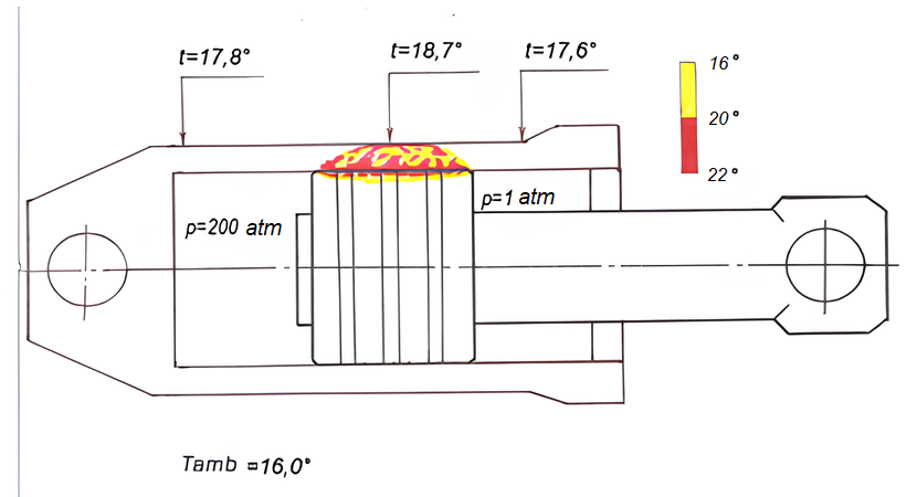
Figure 2 - Model of the internal state of the piston and cylinder
In addition to these, the thermal imaging method allows identifying some other internal defects of hydraulic cylinders.
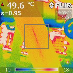
Figure 3 - Incipient defect (burrs of the inner surface of the cylinder)
Internal defects in hydraulic devices, such as valves, spools, distributors, etc., also significantly reduce the efficiency (mainly volumetric and hydraulic) of the hydraulic drive of excavators. As a result of internal overflows in these devices, an abnormal early communication of high-pressure lines with discharge lines occurs. In addition to the loss of power, this also leads to incorrect operation of the shutoff and control elements of the entire drive: instead of smooth controlled movement of the actuator, its operation is jerky, ragged, with deceleration and acceleration, which parameters are sometimes beyond the control of the excavator operator. Fig. 4 shows a model of the internal state of the sliding spool valve of the boom lifting/lowering drive.
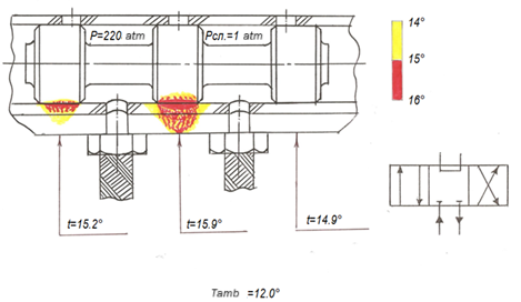
Figure 4 - Model of the internal thermal condition of the sliding spool valve
The possibility of using the thermal diagnostic method to detect hidden defects in power hydraulic cylinders is illustrated in Fig. 5. Thus, while in Fig. 5a (in “the rod is completely retracted the hydraulic cylinder” position), the thermal conditions of the sealing assembly of the hydraulic cylinder and the cylinder rod of the dipper stick are uniform and correspond to the general thermal conditions of the unit itself, in Fig. 5b in “the rod is extended by 50% of its stroke” position, there is a distinct pattern of high temperature of the surface of the stem seal and the cylinder cover with a temperature difference of up to 1 °C. In Fig. 5c in the “rod extended to the end” position, the temperature again acquires a uniform character, without focal bursts of heating of the mating surfaces. Such a picture of the thermal condition of the lip seal assembly of the hydraulic cylinder cover and its stem may indicate the presence of local leaks in this sealing assembly precisely in the middle of the stem stroke, i.e. when its transverse linear deviation from its own axis of symmetry is maximum. This can only happen in the case of a curvature of the cylinder stem, which occurred earlier under the influence of extreme loads with the maximum elongated position of the dipper stick with the bucket. As a result of the pressure of the curved surface of the rod on the lip assembly, the gap opens on the opposite side of the “lip-cylinder cover” seal pair, which causes additional leaks of the hydraulic fluid, the heating of which is recorded by the thermal imager.
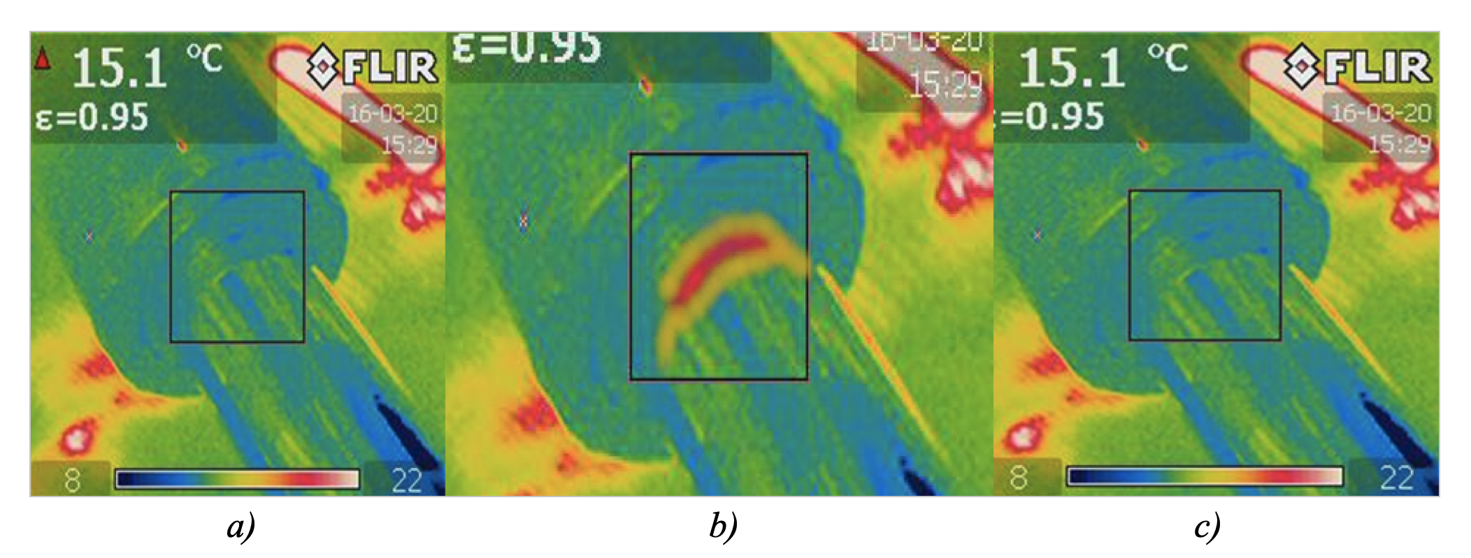
Figure 5 - Curvature of the cylinder rod:
a) “the rod is completely retracted the hydraulic cylinder” position; b) “the rod is extended by 50% of its stroke” position; c) “rod extended to the end” position
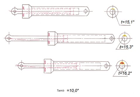
Figure 6 - A model of the internal thermal condition of the rod and the outer lip assembly of the hydraulic cylinder
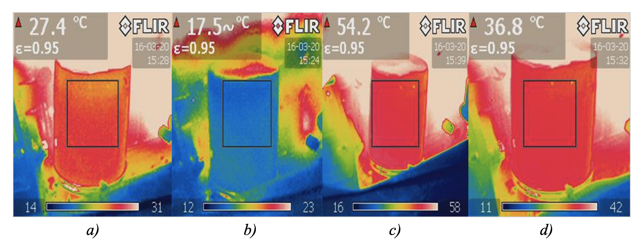
Figure 7 - Diagnostics of filter contamination
Another area of application of the thermal imaging diagnostic method is the prevention of high-pressure hose bursts.
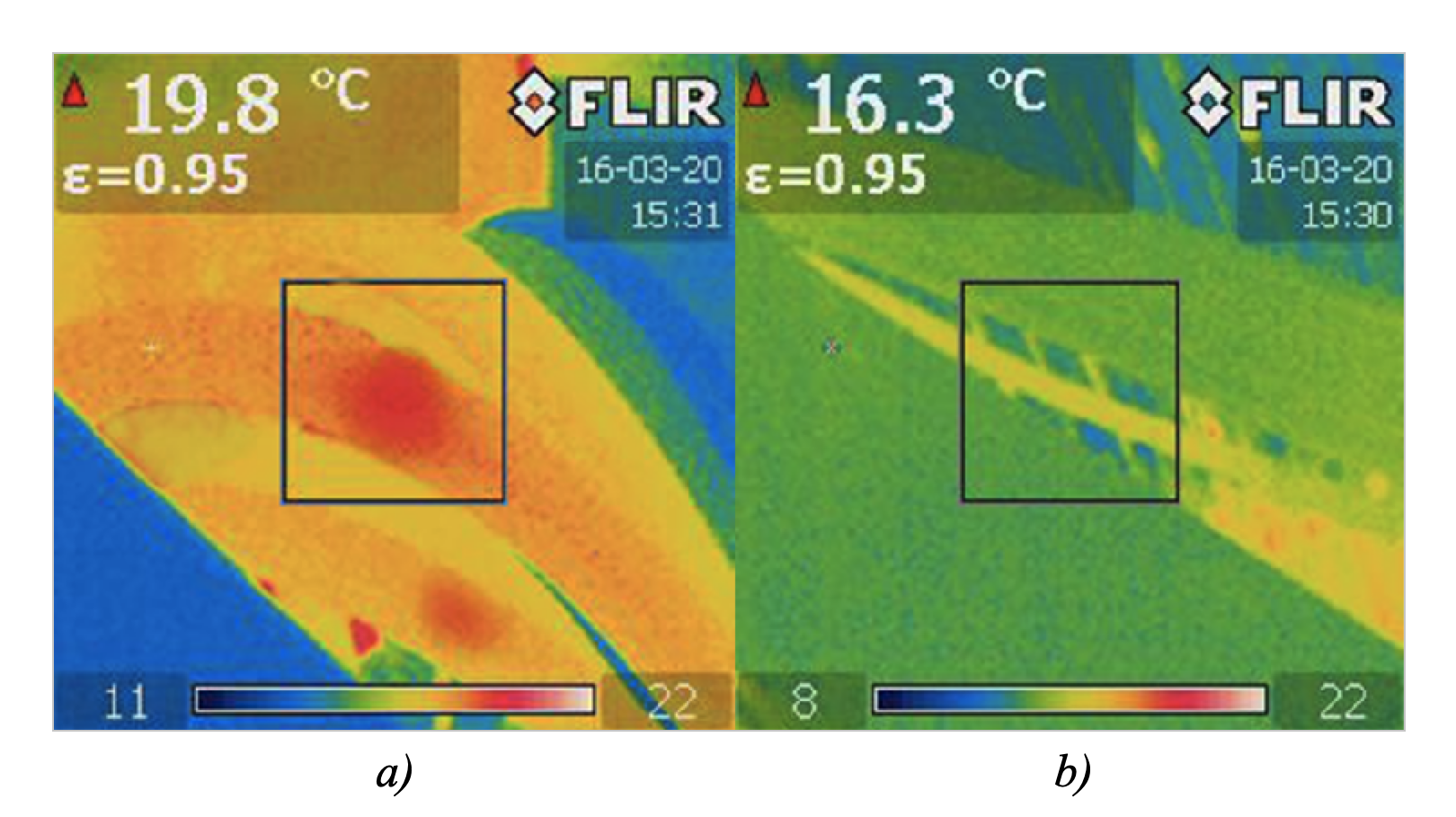
Figure 8 - Diagnostics of high-pressure hose bursts:
a) thermal picture of the internal condition of four high-pressure hoses located in parallel and under operating pressure; b) an example of the normal state of the hose
Thus, the application of the thermal imaging method of operational diagnostics of hydraulic drives of hydraulic excavators allows:
– in a short period of time (no more than 1–2 shifts), getting a picture of the general technical condition of all the main and auxiliary hydraulic drives of an operating excavator;
– compiling a real defective list of hydraulic systems and shut-off and control devices of the excavator being prepared for scheduled repair;
– adjusting the planned shutdown time of the excavator for its repair, both in the longer term and in the shorter term;
– optimizing the costs of the upcoming repairs, in advance, with a certain vision, by logistical preparation for this repair;
– accurately, up to one shift, predicting the duration of the upcoming repair impact.
3. Conclusion
The possibilities of the proposed type of diagnostics can be expanded by introducing elements of artificial intelligence, such as accumulating an array of statistical data, followed by analysis and prediction of pre-emergency situations for the studied assemblies and mechanisms. In this case, it is proposed to have continuous thermal imaging monitoring of the assemblies discussed in this article among the entire fleet of hydraulic excavators actually operating at a particular mining or coal enterprise. The procedure of such monitoring was developed by the specialists of Tyazhmashservis. The main parameters of this technique are filling in temperature values according to the survey route maps and transmitting them to the processing server. In addition, data is added on the current operating time, total loads and accumulated productivity of a particular excavator, and a number of other data (ambient temperature, total service life of the observed excavator, its actual availability coefficient, etc.). The considered thermal imaging diagnostic method has another advantage: it can identify a potentially dangerous defect in the dynamics of its development by measuring the temperature conditions of the same assembly after several cycles of its operation. If the thermal field rises during its operation, there is a real opportunity to predict the beginning of a pre-emergency situation. The developed digital program (of the “digital override” type) makes it possible, based on the statistical data downloaded from such route maps, to provide a fairly accurate forecast of the technical condition of the monitored assemblies and warn about the possibility and timing of their failure.
The key aspects of this article are unique in terms of scientific novelty, namely:
– the use of an operational thermal imaging diagnostic method to search for early defects in hydraulic drive elements of large-capacity quarry hydraulic excavators;
– the opportunity to use an automatic robotic diagnostic system in a mining enterprise based on the collection and processing of statistical data and introduction of artificial intelligence systems based on early warning of failure of the main components and mechanisms at large mining enterprises.